All images and information used with permission of Delta Air Lines.
Pressure Decay Testing Fixture
Situation
As a task in the assembly procedure of the Turbine Intermediate Case (TIC) within PW1000-series turbofan engines, two tubes for the No. 4 Bearing are tested for pressure decay. If the test is failed, the TIC must be disassembled to diagnose the source of the pressure decay, which takes 2-3 days of work. The shop has noticed that the tubes themselves are typically the source of the pressure decay, rather than issues with assembly.
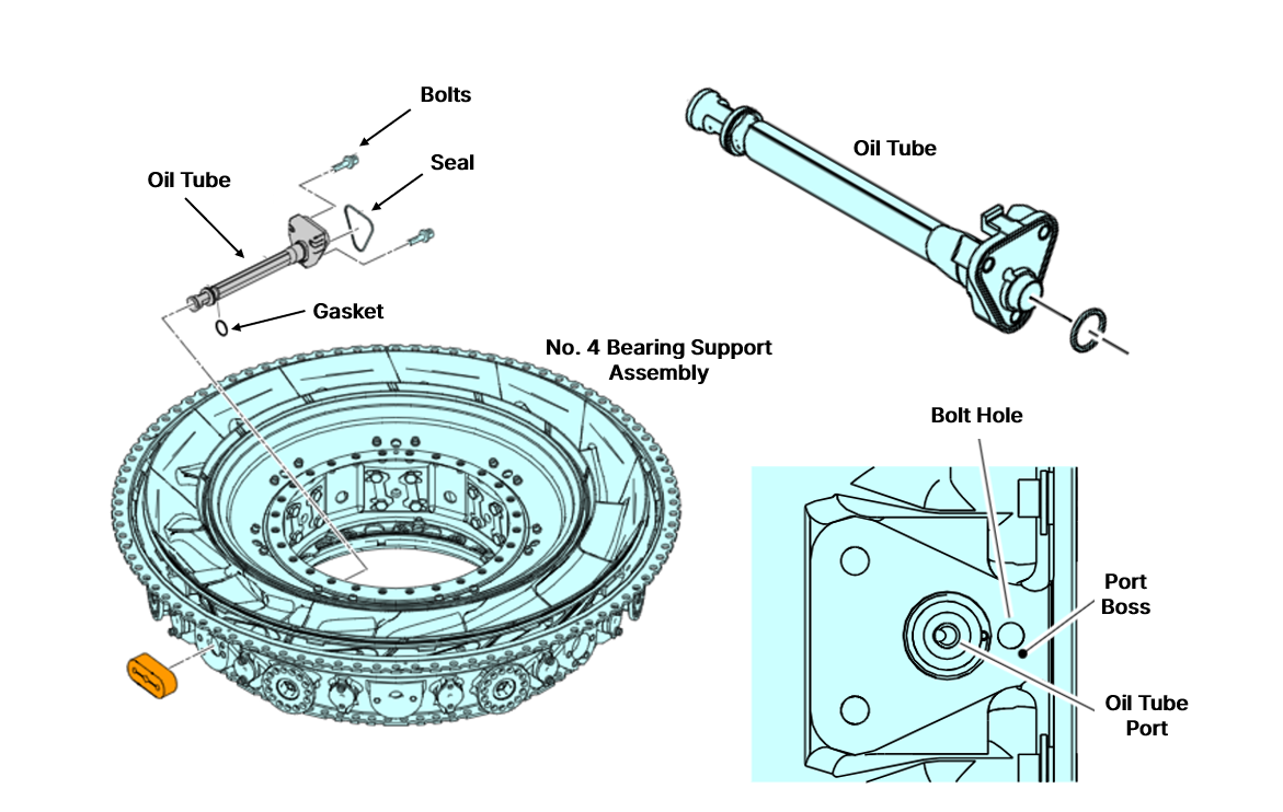
Illustrations of the No.4 Bearing Support Assembly, Oil Tubes and Tube Ports.
Workflow
- Using a 3D scanner, I created STLs of the geometries of the two ports on the No. 4 bearing where the Oil Supply Tube and Oil Scavenge Tube connect.
- Using DesignX, I used the STL mesh geometries to extract features and create editable solid CAD models matching the ports’ geometries.
- I modified the models to create a blank for each tube port that can be mounted to a test bench, allowing the tubes to be tested for pressure decay using the manufacturer’s procedure outside of the assembly.
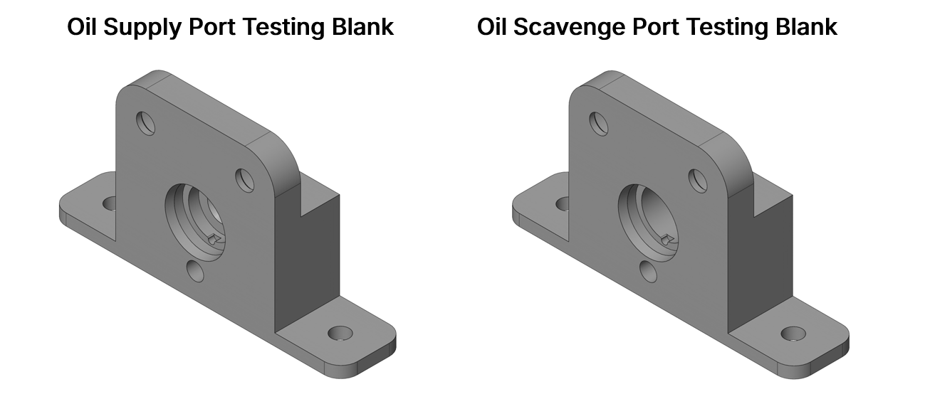
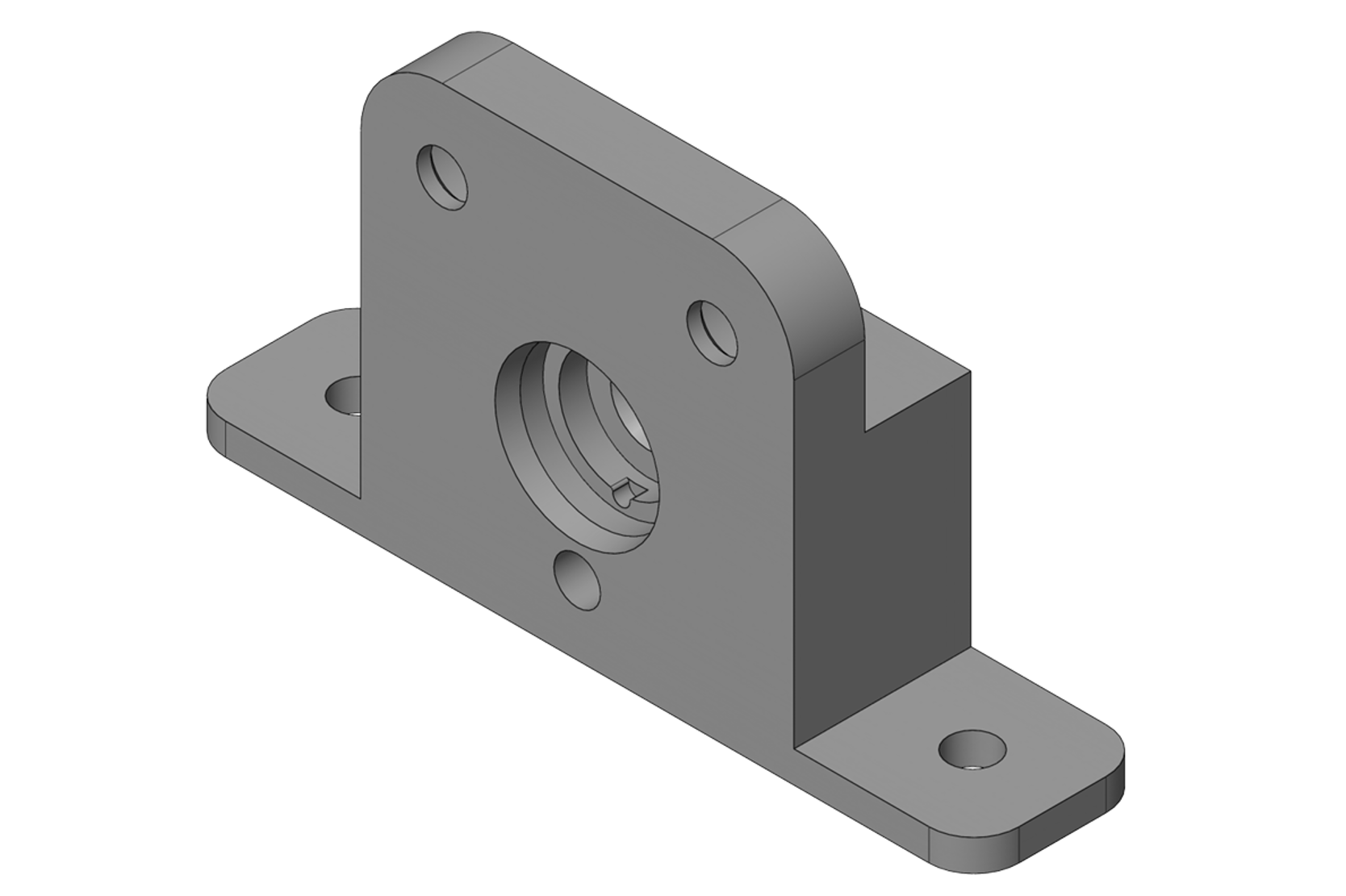
Final CAD models of the testing blanks for validating tubes outside of the assembly.
Progress
The pressure decay testing blanks are currently being machined with the manufacturing drawing package I created, and they will prevent multi-day setbacks in assembly when Oil Supply and Oil Scavenge Tubes are faulty. Pressure decay test failures in the assembly process can be attributed to assembly issues rather than faulty tubes.